You are using an out of date browser. It may not display this or other websites correctly.
You should upgrade or use an alternative browser.
You should upgrade or use an alternative browser.
midget rack
- Thread starter tigermike
- Start date
Rack and pinion
I would suggest you go to CLASSIC MOTORSPORT MAGAZINE website and read the Sunbeam Tiger articles under their COMPLETED PROJECTS. Cleo Shelby's Tiger has a Mazda Miata rack and pinion. I don't recall any article or threads on the Mazda rack and pinion. On Classic Sunbeam website are articles are about using a Mustang rack and pinion. Others have used a Flaming River rack and pinion. Gather information and then decide whether it fits your particular application. The ultimate situation is to replace the original Tiger crossmember with Dale A's fabricated crossmember when you have $$$$ to burn.
I would suggest you go to CLASSIC MOTORSPORT MAGAZINE website and read the Sunbeam Tiger articles under their COMPLETED PROJECTS. Cleo Shelby's Tiger has a Mazda Miata rack and pinion. I don't recall any article or threads on the Mazda rack and pinion. On Classic Sunbeam website are articles are about using a Mustang rack and pinion. Others have used a Flaming River rack and pinion. Gather information and then decide whether it fits your particular application. The ultimate situation is to replace the original Tiger crossmember with Dale A's fabricated crossmember when you have $$$$ to burn.
- Messages
- 2,862
Racking Opinions
I've done a couple and the correction is noticable a bit, but does not fully address the ackerman dangle issue. It will also increase the parking lot steering effort because of ratio loss. We did one with just the MG arms part of the solution and kept the original Tiger rack with end adaptors. It was very nice, and I noticed the tire drag in a reversing corner was much less. For normal driving and outings, I don't see the need to throw another umpteen euros under the front end. But then, the boys do offer some neat stuff and it sure looks good.
Looking for feedback from members who have had experience with installing the mg midget rack on a Sunbeam Tiger.Is it difficult to install it correctly and are the results worth the effort
Thanks
Mike")
I've done a couple and the correction is noticable a bit, but does not fully address the ackerman dangle issue. It will also increase the parking lot steering effort because of ratio loss. We did one with just the MG arms part of the solution and kept the original Tiger rack with end adaptors. It was very nice, and I noticed the tire drag in a reversing corner was much less. For normal driving and outings, I don't see the need to throw another umpteen euros under the front end. But then, the boys do offer some neat stuff and it sure looks good.
66TigerMK1A
Gold forum user
- Messages
- 1,130
Well... I have a Mazda power rack similar to the one in Cleo's car... it's actually driven by a Toyota MR2 electric hydraulic pump located in the wheel well. No matter which rack you put on the stock cross member...at least without major surgery, it will do nothing for the ackerman angle as you can't really relocate it's position ( front to back) much. The key to the 'Midget Rack' swap is the fact that it uses MGB steering arms which are at least 5/8" longer ( further forward ) than the stock arms. For correct ackerman angle, for a given inside wheel angle ...say 20 °... the outside wheel should be at about 17 °. The stock setup will give you an outside wheel angle of about 22.17° which means that the wheels are toeing in as you turn. If you use the MGB arms, you will get an outside wheel angle of about 21° which is better... but not great. The outside wheel to track correctly should always be turning at a smaller angle than the inside wheel. At the extreme, say when the inside wheel is at 30°,the outside wheel is at about 36+° ( correct ackerman is 24°)with the stock setup which is probably why there's been a few fulcrum pin failures...especially when backing up ! I've actually re-created the old ' Lou Anderson accurate ackerman angle ' fix on my car and I have pretty much perfect ackerman angles when turning ! Having said that, I'm not sure, 'in the real world' if that's the perfect setup as my car turns in very easily and with 400 hp to bring the back end around anyway, you can get into over steer before you know it ! The other down side of that particular ackerman fix is you will create more bump steer no matter how much you tweak all the heim joints. You can see all what I've done to the front end by clicking on my name and having a look at some pics in my albums. As Randy says, you can go out and get one of Dales or Mikes 'killer' crossmember setups but be prepared to spend some serious coin ! I think if I had to do it all again I would just put in the MGB arms, keep the Tiger rack... and maybe get one of those 'power' steering columns the UK boys are having built now !
Jim
B382000446
Jim
B382000446
cadreamn67
Platinum Forum Member
- Messages
- 608
+1 on everyone's posts.
FWIW, at least a few months ago , I heard that Dale A. was out of the adapters for the MG Midget rack and there was no restocking plans. However, there was someone in the UK that might be still making their version available. So this may be more of an academic discussion than a practical choice.
As for installation, I looked closely at the tigersunited.com article by Larry Paulick done in April, 2002 when I installed mine a couple of years ago. However, I did not remove my crossmember to do it. Just pulled the radiator. Also, I do not see how the inner tie rods (inside the boots) can get properly lubricated with using Mobil 1 grease as he suggested. So I went with an 85W-90 Gl-4 gear oil. (factory spec back in the day was 90 wt. gear oil). I recommend the GL-4 because the rack has brass dampner pads that that GL-5 oils typically attack (like they do manual trans brass syncros...)
I am surprised that apparently no one has ever followed up on the Doane Spencer modification that is described in Larry's article. Or maybe it has been done and I am in the 10% that never get the word on things from time to time. Anyone have any info on that fix (mitigation) to the Ackerman Angle problem?
Gene
66TigerMK1A
Gold forum user
- Messages
- 1,130
I think I heard that Dale's adapters were NLA quite a while ago ( a couple years? )... the UK ones are I think about twice the price but still available...
I've looked at those pics of Doanne Spencer's setup many times and read the description but still don't understand exactly what was done... 'flipped the rotors' doesn't compute for me.... not enough information lol
Jim
B382000446
I've looked at those pics of Doanne Spencer's setup many times and read the description but still don't understand exactly what was done... 'flipped the rotors' doesn't compute for me.... not enough information lol
Jim
B382000446
Tiger tamer
Gold forum user
- Messages
- 318
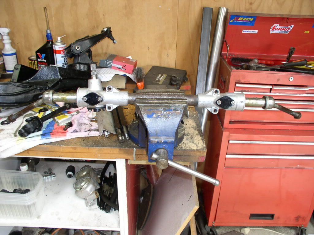
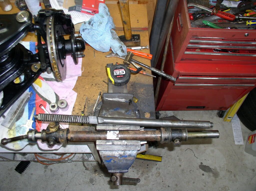
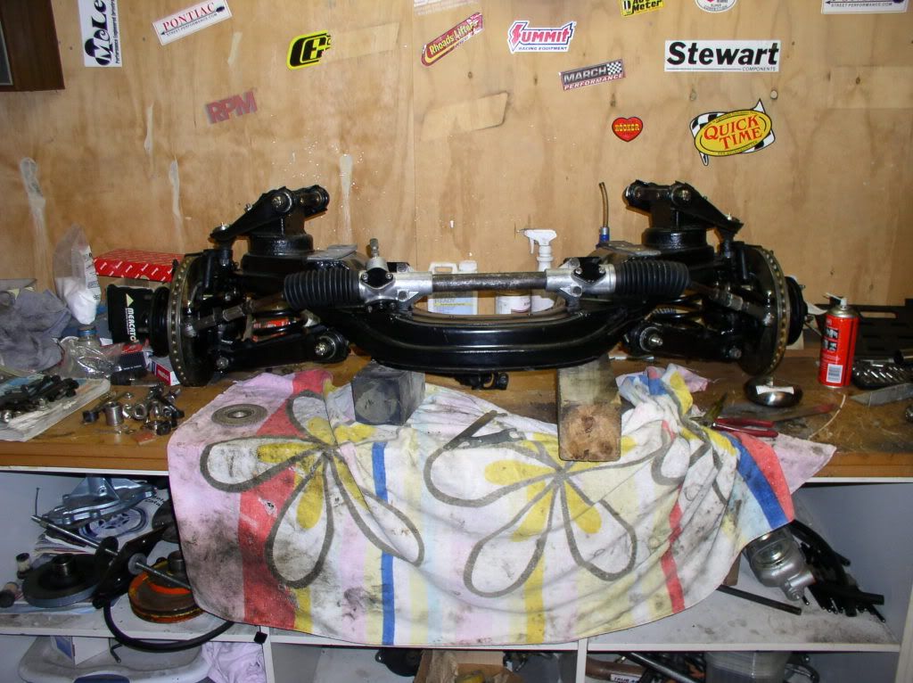
I used the Tiger rack case with a modifided Morris Oxford rack and a custom built pinion. Long story on why I used a Oxford rack instead of a Midget rack, but they measure the same. This gave me the same ratio as the midget rack but in the Tiger casing which bolts straight in. I end up with the straight rack arms and am using MGB steering arms, which should give me the same improvement as the Midget rack set up.
Car is still not completed yet so the rack is untested.
Car is still not completed yet so the rack is untested.
Last edited:
- Messages
- 2,862
Tamer Experiment
On Tiger Tamer's solution: Is the Morris Oxford rack ball-to-ball length same as the Tiger rack? If so,, given parts standardization, could the Morris' straight ends be put on the Tiger's rack thus keeping the better steering effort ratio . . . .. . .just learning & curious.
On Tiger Tamer's solution: Is the Morris Oxford rack ball-to-ball length same as the Tiger rack? If so,, given parts standardization, could the Morris' straight ends be put on the Tiger's rack thus keeping the better steering effort ratio . . . .. . .just learning & curious.
Tiger tamer
Gold forum user
- Messages
- 318
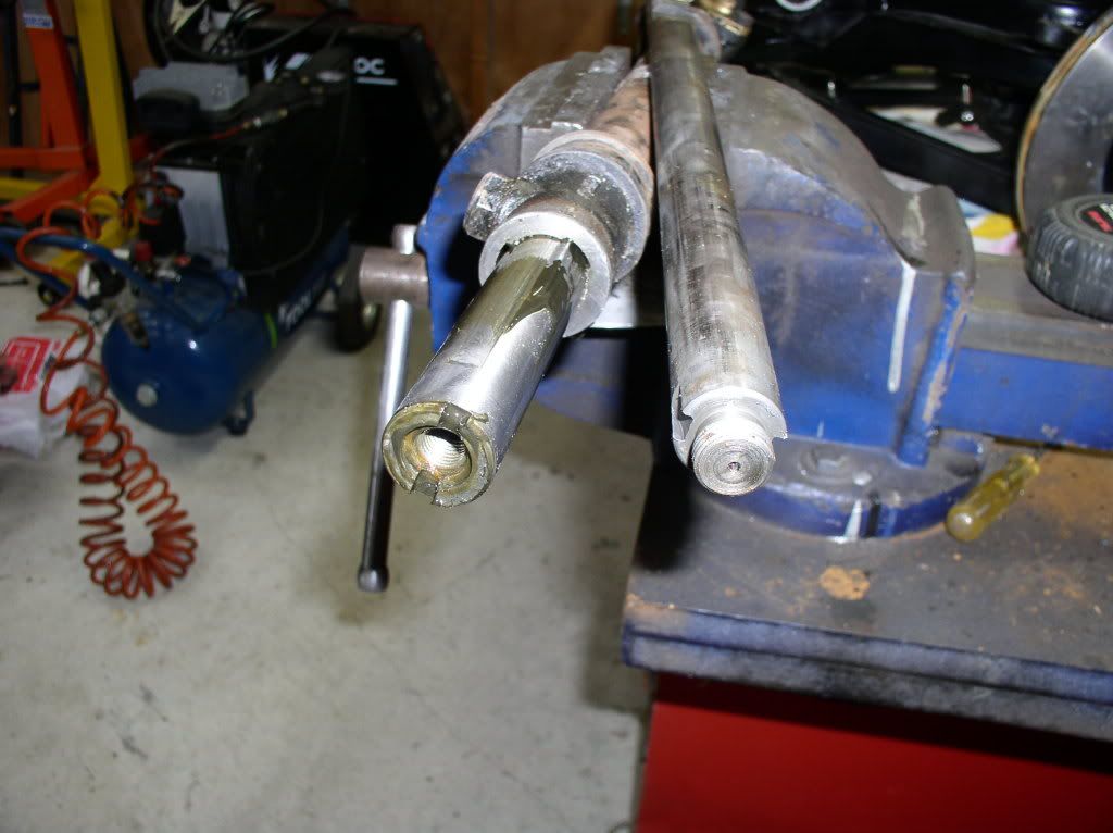
The Oxford rack is a little longer and the thread internal as well.
On the Tiger rack they would have had to make the thread external as the rack teeth are cut to the end. Also the Oxford rack was a larger dia and had to be turned down to the Tiger dia.
Lots to digest here but worth the read if you're really interested in a cure for the Ackerman problem:
http://www.mayfco.com/steering.htm
Particularly interesting is Mayfield's assessment of the Midget rack solution:
"The maximum benefit gained, at full lock of 26 degrees, is only 2 degrees. This is not enough of a gain for me - another 7 degrees is needed!"
Mike's solution was to build a new crossmember moving the rack back. In 2005 I calculated it took 8 feet off my turning circle.
Bob
Midget Rack
I have just spent a bit of time correcting bump steer on my Tiger. When I purchased the car it had the Midget rack and MGB steering arms fitted. After having driven it on the open road for about 1600 miles constant movement of the steering wheel, quite violent when encountering bumps, forced me to look closely at what was happening. I set up a rough jig (broomhandle strapped to the wheel) and jacked the car up until the wheel almost left the ground, and then measured the movement at the end of the broom stick. It had almost 50 mm toe in per wheel which worked out to be in excess of 4 degrees on rebound, and probably an equal amount of toe out on bump. Moving the rack would have been a last resort, so I played around with the arms to see what could be acheived. In the end I turned the arms upside down and swapped them from side to side. I made up 2 tapered sleeves with 7/16" bores, which take 7/16 HT bolts, to fit inside the end of the arms, and made up new adaptor ends with F/M 5/8" RH threads and 7/16 LH threads and fitted spherical 7/16 male l/h rod ends. By shimming these down .200" below the steering arm, I virtually eliminated all the bump steer. If I played with the shims a bit more it would be possible to eliminate it completely, but at the moment i have about 3 mm change at the end of a 900 mm broom handle over full rebound, so thats close enough for me. I think the ackerman angle could also be improved by shimming out the back of the steering arms a little. From what I remember from my apprenticeship days, lines drawn rearward through the centreline of the steering arms should intersect around the centreline of the diff.The car is now totally different and much less darty to drive, particulary under hard acceleration, and the best thing of all it cost very little to fix.
I have just spent a bit of time correcting bump steer on my Tiger. When I purchased the car it had the Midget rack and MGB steering arms fitted. After having driven it on the open road for about 1600 miles constant movement of the steering wheel, quite violent when encountering bumps, forced me to look closely at what was happening. I set up a rough jig (broomhandle strapped to the wheel) and jacked the car up until the wheel almost left the ground, and then measured the movement at the end of the broom stick. It had almost 50 mm toe in per wheel which worked out to be in excess of 4 degrees on rebound, and probably an equal amount of toe out on bump. Moving the rack would have been a last resort, so I played around with the arms to see what could be acheived. In the end I turned the arms upside down and swapped them from side to side. I made up 2 tapered sleeves with 7/16" bores, which take 7/16 HT bolts, to fit inside the end of the arms, and made up new adaptor ends with F/M 5/8" RH threads and 7/16 LH threads and fitted spherical 7/16 male l/h rod ends. By shimming these down .200" below the steering arm, I virtually eliminated all the bump steer. If I played with the shims a bit more it would be possible to eliminate it completely, but at the moment i have about 3 mm change at the end of a 900 mm broom handle over full rebound, so thats close enough for me. I think the ackerman angle could also be improved by shimming out the back of the steering arms a little. From what I remember from my apprenticeship days, lines drawn rearward through the centreline of the steering arms should intersect around the centreline of the diff.The car is now totally different and much less darty to drive, particulary under hard acceleration, and the best thing of all it cost very little to fix.
the_tool_man
Gold forum user
- Messages
- 196
On Classic Sunbeam website are articles are about using a Mustang rack and pinion.
Hmmm...I happen to have a Mustang power steering rack sitting in my garage. Can't find the article you mention. The only Classic Sunbeam website I can find is the parts seller. Care to be more specific?
TigerBlue
Gold forum user
- Messages
- 827
Try these for Classic
"The only Classic Sunbeam website I can find is the parts seller?"
Links below. There are many tech articles in archives of Tigers United and The Motorsports mag has a project Tiger.
http://classicmotorsports.net/
http://www.tigersunited.com/
Rick
"The only Classic Sunbeam website I can find is the parts seller?"
Links below. There are many tech articles in archives of Tigers United and The Motorsports mag has a project Tiger.
http://classicmotorsports.net/
http://www.tigersunited.com/
Rick
Last edited:
cadreamn67
Platinum Forum Member
- Messages
- 608
grelley,
Any pictures you can share would be greatly appreciated. I also have the MG rack setup, but do not seem to have quite the same degree of problems you described.
You mentioned that you switched the arms from left to right. I cannot help but wonder if the PO had them installed wrong in the first place. Per the www.tigersunited.com tech article, they should be installed switched from how they are they are installed on the MG (e.g., left side arm goes on right side, etc.). Are you saying they are now installed unswitched and that is working better?
I for one would be very interested in comparing pic's of what you have come up with to what is shown in the tigersunited site article, which is how mine look.
Gene
Tiger tamer
Gold forum user
- Messages
- 318
grelley,
Any pictures you can share would be greatly appreciated. I also have the MG rack setup, but do not seem to have quite the same degree of problems you described.
You mentioned that you switched the arms from left to right. I cannot help but wonder if the PO had them installed wrong in the first place. Per the www.tigersunited.com tech article, they should be installed switched from how they are they are installed on the MG (e.g., left side arm goes on right side, etc.). Are you saying they are now installed unswitched and that is working better?
I for one would be very interested in comparing pic's of what you have come up with to what is shown in the tigersunited site article, which is how mine look.
Gene
I too would love to see some pic's. I have used the the Tiger rack case with a Oxford (same dimensions as a Midget ) inner rack and a new pinion cut to suit. MGB arms mounted upside down and Alpine tie rod ends. I still need to have the adapters made up to join the tie rods on.
Cheers Mal.
Last edited:
Steering Rack
I will get some photos, but at the moment the tapers in the arms are facing down ie the narrowest part of the taper is at the bottom. This lifts the end of the steering arm up. Previously they were the opposite way around, Perhaps I have just rediscovered what everyone else knew.
I will get some photos, but at the moment the tapers in the arms are facing down ie the narrowest part of the taper is at the bottom. This lifts the end of the steering arm up. Previously they were the opposite way around, Perhaps I have just rediscovered what everyone else knew.
- Messages
- 907
To clarify the "flipped rotors" that Doanne used:
I own a set of Doanne's racing knock-offs, complete with HSC wheels and his reversed caliper set-up.
The stock brake caliper is mounted on the inside of the spindle in Alpines and Tigers. The rotor is dished, with an offset between the surface where the rotor mounts to the hub. In the stock position the rotor is offset to inside of the car.
For some reason that I have never understood, Doanne moved the caliper outboard by bolting it to the outside surface of the caliper. (he also cut about .100" from the mounting surfaces on both the caliper and on the spindle).
He removed the rotor from the hub and reversed it so that the offset now had the rotor outboard of the mounting surface on the hub. The rotor then center nicely inside the caliper.
I've tried using Doanne's setup but then returned to the stock location mainly because it allows much more cooling air to flow over the rotor and caliper since they are not tucked inside the wheel as much as they are using Doanne's outboard location.
I've used the MG arms with the rotor in either location successfully.
Good luck,
bt
66TigerMK1A
Gold forum user
- Messages
- 1,130
Interesting... I just went out to the shop and had a look at a couple MGB arms... it looks like you've gained about 1/2" and the rod end is also closer to the arm than a ball joint would be so even more gain there... I don't have a Tiger arm handy but do recall that the end of the arm swept 'up' a bit.
I'm guessing your car is not lowered at all if you had to move the tie rods up... I'm running Minx spindles and have the car lowered even further so I had to get the tie rods down using a bump steer stud that fit the MGB arm.. and then used a 5/8" female rod end rated at 18k lbs. static... I always rather err to the 'stronger' than the 'weaker' parts, especially for steering. I had a look at the spec on a QA1 XML 7 -7/16 x 7/16 Endura male rod end and the static load was rated just over 10k lbs. ... the same rod end ( XML 7-8 ) with a 1/2" thread was almost 19k lbs.
Buck, that a great explanation of Doanne's setup.. I've looks at some pics of what was supposed to be his setup and I didn't understand it at all... I suppose if that enabled the steering arm pivot to be moved outward then it would greatly help the ackerman problem...
Jim
B382000446