You are using an out of date browser. It may not display this or other websites correctly.
You should upgrade or use an alternative browser.
You should upgrade or use an alternative browser.
Researching LAT Tri-Y headers
- Thread starter ojxxx
- Start date
- Messages
- 333
According to the BON, the Cobra Tri Y's were only 3+ horsepower difference over stock manifolds, but the Tiger Tri Y's were reworked by Doane Spencer and gave a 6hp+ over the Shelby "Huth" tube (only 19hp over stock manifolds) headers to give a total 25hp over the stock exhaust manifolds. I like mine, they do come close to the frame though.
Brian
Brian
I agree, there is something different, the engine bay smaller? this is a Mk1 are they all the same? What I'm doing is working on the bench mockup, taking everything apart and installing it all inside the car to check things and taking it all back apart to go back on the mockup, thats why progress/photos are so far apart. I meant to take a photo the last time it was in the car, its so tight in there that 2D photos get confusing.I'm wondering if when you have the motor mount and chassis mount bolted on like that, they sit in the same position as they would in the car with the weight of the engine on them and flexing of the motor mounts. I believe the LAT chassis mount was modified more for clearance of the down-tube than clearance of the manifold itself.
Can you get a measurement from the outside of the chassis mount to the outside of the one on the other side and compare it to the dimension between the frame rails where they bolt in? I think it's possible it might be pulled in a little in your photo.
Warren
Gold forum user
- Messages
- 3,872
The 53 code car in the Woodley Park pictures has a set. Dan W. AKA spmdr fitted the set after copying a serial Tiger hoarder's original down tubes hangers and manifolds.
IDK where the tale came of the Tri-Ys being installed upside down on an engine Dyno but the result is that they still are cool and different. Be nice to see the documentation regarding the upside down test.
An extra added plus is what would the deduction be in stock for a original or reproduction set installed as they were in period.
- Messages
- 335
As far as I know that dimensions between the frame rails are the same. It's obviously very tight there. Even if the car had taken a hit at some point, it's hard to imagine the rails getting pinched in with the engine sitting between them acting as a brace.
Slightly off topic and not to suggest anything but there is a Tiger with a Boss 302 that was featured in one of the books years ago and has been on eBay recently and the description said the engine hangers were modified to bolt outside of the frame rails instead of inside to give more clearance. I haven't seen photos but it's an intriguing thought.
Slightly off topic and not to suggest anything but there is a Tiger with a Boss 302 that was featured in one of the books years ago and has been on eBay recently and the description said the engine hangers were modified to bolt outside of the frame rails instead of inside to give more clearance. I haven't seen photos but it's an intriguing thought.
When I originally put this car together a couple years ago we did some chassis dyno pulls and we'll put it back on the same dyno to get some before/after headers swap numbers.
Heres the tentative mockup of the left side, I have some tweeking to do to it yet.

Heres the tentative mockup of the left side, I have some tweeking to do to it yet.
Here's a photo that shows the interference between the cast header and chassis mount, there is a large gap at the motormount to the chassis mount, I have another photo with a 3/8 bolt laying in there for scale. To get the motormount to seat onto the chassis mount I made the new chassis mount with just the 2 holes. Yes, that motormount is the old one and is slightly compressed and I have a new one to replace it but the difference between them is not significant.As far as I know that dimensions between the frame rails are the same. It's obviously very tight there. Even if the car had taken a hit at some point, it's hard to imagine the rails getting pinched in with the engine sitting between them acting as a brace.
Slightly off topic and not to suggest anything but there is a Tiger with a Boss 302 that was featured in one of the books years ago and has been on eBay recently and the description said the engine hangers were modified to bolt outside of the frame rails instead of inside to give more clearance. I haven't seen photos but it's an intriguing thought.
- Messages
- 335
ojxx,
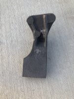
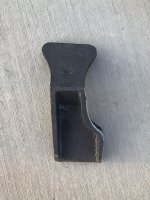
In case you're interested, I got my first samples from the foundry of the reproduction LAT chassis mount. They do not address the issue you are having with interference between the manifold and the top forward mounting hole but they do have clearance for the down pipe, same as the originals.
Some finish work still needs to be done and the holes need to be drilled and tapped.


Last edited:
I assembled everything for a final mockup in the car and I didn't care for it. The headers dropped down too low so I took it all back apart, cut the headers apart and shortened them by about 2", heres a mockup on the bench with the new PowerMaster Starter:

I've ordered some stainless flanges to mate these to the exhaust, hopefully they'll be here tomorrow.
There's a problem I see in the final mockup, I have no idea how I'll get that one bolt from the front tube into the Y castings, its behind the chassis mounts as if I have to take them out to get it up in there. It's a puzzle.
Well, here they are

I wound up using a 'V' band clamp instead of the flanges. To bolt the headers up I have to take the motor & chassis mounts off, bolt these to the castings, assemble the motor & chassis mounts and let the engine down then run the bolts into the chassis mounts. The starter bolts up without messing with the headers.
I wonder if these replacement motor mounts are at the right angle? They'll bolt up because of the rubber but I believe that that is the root cause of the chassis mount/header interference? When I bolt the chassis mount to the frame the motor mount stud passes thru it but the mating surface angles are off.
On the drives' side I made motor mount travel limiters from countersunk 5/16ths stainless bolts so it seats flush to the chassis mounts (the 'V' band clamps are also in the photo:
To complete the headers I had to relocate the oil filter, the owner wanted it inside the left fender, behind the headlight. I planned to use the filter adapter from Earls and make stainless tubing to the remote housing but the bends were too tight and I used stainless braid hose & fittings.

This is the remote filter adapter and the makings for its' mounting bracket

I bent the bracket added a strap brace and welded in some mounting studs

Here's a mockup of the assembly with the -AN bulkhead fittings


This assembly gets mounted inside the fender, the left headlight cable gets pulled back and the hole gets enlarged for the left bulkhead fitting, holes drilled for the right bulkhead and mounting studs. The hose is -10AN nylon with internal stainless braid, a little more flexible than typical stainless braid

And the filter

This is the remote filter adapter and the makings for its' mounting bracket
I bent the bracket added a strap brace and welded in some mounting studs
Here's a mockup of the assembly with the -AN bulkhead fittings
This assembly gets mounted inside the fender, the left headlight cable gets pulled back and the hole gets enlarged for the left bulkhead fitting, holes drilled for the right bulkhead and mounting studs. The hose is -10AN nylon with internal stainless braid, a little more flexible than typical stainless braid
And the filter
