Adding A/C....let's discuss it

I'm still working on this. I also had the engine out for rebuilding, added the electric power steering, and fuel injection, so lots to keep busy with.

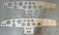
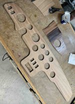
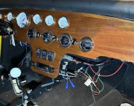
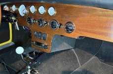
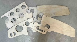
I've made a new dash. I cut it on a laser cutter that is not large enough to do it in one piece. So I cut it out in sections in 2 layers. One layer is 1/4" plywood and the other is 1/8" plywood; the seams are staggered. I have to cover it with veneer and then finish it.

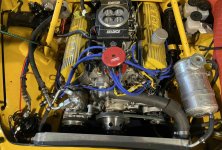
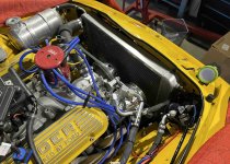
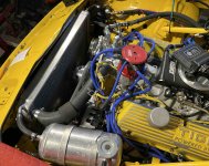
The condenser is going in front of the rad. I really didn't like the idea of it being over and/or in front of the rear axle. Though it does have the advantage of not adding heat to the engine compartment, I think running 2 refrigerant lines from there to the engine compartment would be a real pain. And ducting cooling air to it also means ducting road crap into it.

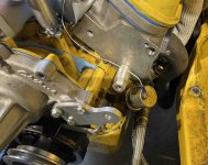
I considered various places to mount the compressor. There is actually room above/outside of the alternator, and also below it. But I couldn't see how to run a belt to it. So I'm swapping the alternator to the other side of the engine and the compressor will go where the alternator was. There is more room for the compressor on that side and the hose run is more direct to the evaporator. I'm making the brackets and hardware needed for the swap now.

Rick

Edit: I'll continue the dashboard assembly and finishing in another thread
Screenshot 2024-06-06 at 2.52.29 PM.jpg

Screenshot 2024-06-06 at 2.52.19 PM.jpg
 
Last edited:
Swapping the alternator to the left side.

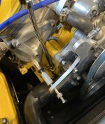
There are some threaded holes in the end of the head, as well as the water pump mounting bolts, to use for new brackets. Made the bracket and an extra part to adapt the long 7/16" alternator mount bolt to the head.

Screenshot 2024-06-10 at 7.43.51 PM.jpg

The alternator fits here nicely:

Screenshot 2024-06-18 at 5.57.59 PM.jpg

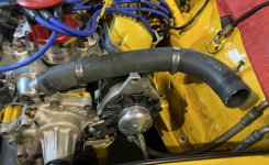
Of course I forgot about the upper rad hose:

Screenshot 2024-06-10 at 7.44.27 PM.jpg

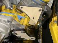
The alternator needed to be about 2" lower to clear that. So, new brackets....this time mocking them up in wood first:

Screenshot 2024-06-10 at 7.44.45 PM.jpg

Screenshot 2024-06-10 at 7.45.07 PM.jpg

I got the correct size belt on the 3rd try:

Screenshot 2024-06-18 at 6.02.58 PM.jpg

The rad hose almost clears it now. Could have moved the alternator maybe 1/2" lower. I can machine off part of the lug that is contacting, or put some form of anti-chafing spacer between them. I could reroute the hose, but I'll leave that for now. The rad is in along with the puke tank and the all the hoses. I can fill it with water now and run the engine.

Screenshot 2024-06-18 at 6.03.06 PM.jpg

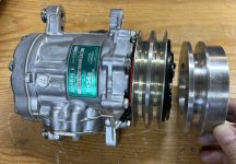
I've mounted the electric fan and trial mounted the A/C condenser. Left the condenser out for now. I also have the compressor now, so after running the engine and making sure everything is OK I can start on the mounting for that. Oh, also the accumulator/dryer and the heater control valve. Lots of hardware in a small space.

Rick
 
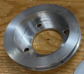
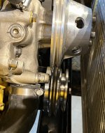
Now that the alternator is on the other side of the engine, I need a pulley to drive the A/C compressor. The easiest way seemed to be to add an additional pulley to the front of the harmonic balancer pulley. Yes, I could have machined a new pulley with 2 grooves in it but that seemed like a huge amount of work, with a decent chance of messing something up. So I machined a pulley that I could attach to the front of the existing pulley. I did mess up along the way, but recovered from it.

This is the existing pulley that bolts to the harmonic balancer.

Screenshot 2024-07-09 at 8.02.05 PM.jpg

Note that it is specific to the 302 roller lifter engine. Thank you "Hoghead" for the advice on what to do. You were right, I could just machine what I needed.

I figured I could machine a pulley that would use the existing bolts to hold the new and existing pulleys in place. It might have worked, but along the way I decided to make the new pulley about the same diameter as the one on the compressor:

Screenshot 2024-06-29 at 7.44.51 PM.jpg

At that point I realized that the existing bolt pattern would be right through the new pulley 'V'. So, I got creative and came up with this:

Screenshot 2024-06-29 at 7.26.03 PM.jpg

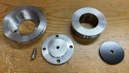
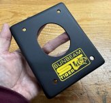
The existing pulley on the left, then a bolting plate that fits into that pulley and uses the existing bolts to hold it and the existing pulley in place. Note that the bolting plate has a threaded hole in it. At the top right is the new pulley, and the black part (powder coated steel) is the cover piece.

The other side of the pulley looks like this:

Screenshot 2024-06-29 at 7.26.15 PM.jpg

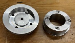
The new pulley on the left with the bolting plate in it, with 1 bolt in place. The counter-bores in the new pulley clear the bolt heads, but prevent rotation. Then the cover plate bolts on with a through-bolt into the bolting plate to hold the pulley in place. Simple, no?

Screenshot 2024-06-29 at 7.27.02 PM.jpg

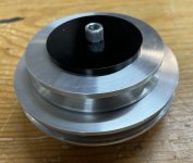
And in place it looks like this:

Screenshot 2024-07-03 at 5.29.51 PM.jpg

Now I have to make mounts for the compressor.

Rick
 
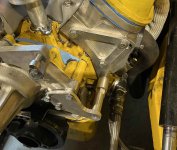
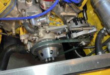
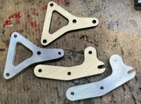
Mounted the A/C compressor. Used threaded holes in the head and the water pump; similar to the alternator mounting.

Prototypes in wood, then the CNC'd aluminum ones:

Screenshot 2024-07-15 at 8.40.38 PM.jpg

Some spacers and a steel adaptor piece:

Screenshot 2024-07-15 at 8.41.08 PM.jpg

Looks almost factory :):

Screenshot 2024-07-15 at 8.42.15 PM.jpg

Need to mount the accumulator/dryer and the heater control valve, then get the hoses and fittings to suit.

Rick
 
Got a lot done on the A/C install.

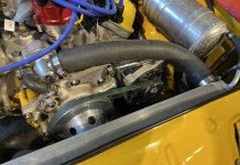
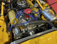
All the components are now in place and I made up the lines. The Vintage Air system of lines that you make up at home (no trips to a hydraulic place to get the fittings crimped on) is really nice. Things are pretty tight with a good size engine in a small compartment, but it looks good and nothing is crammed in at all. I think the last thing is to make a mount for the ignition coil. Not quite enough room for it where it was since I moved the alternator to that spot.

Screenshot 2024-08-12 at 11.43.48 AM.jpg

Screenshot 2024-08-11 at 8.03.47 PM.jpg

Screenshot 2024-08-11 at 8.04.18 PM.jpg

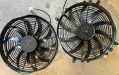
With the fan I had before, a Maradyne M142K 14", I mentioned in my thread on dropping the engine that with the rad in place it didn't seem to blow a lot of air through it. I bought a replacement 14" Spal. These are the 2 of them ( Spal on the left):

Screenshot 2024-08-11 at 8.07.27 PM.jpg

They both appear very similar, but looking closer the Spal has more curve in the blades. Also, from the specs it draws more current. More current should mean more airflow. I couldn't figure a cheap-and-nasty way to test them so I just powered each one up while holding onto the motor. No issue with the Maradyne. The Spal torqued out of my hand a few times until I got a really good grip on it. It seemed to blow more air, but kind of hard to tell. Researching fans, they also have a pressure drop spec that will affect the flow, so some are better with a restriction in front (a radiator) than others.

I powered the new fan up with everything installed. The previous one didn't seem to blow much air through the rad. This one does blow a noticeable amount of air through the A/C condenser and the rad....so should be good. Still have to do some sealing up of areas around the fan.

Did some more work on the dash. I laminated it with mahogany, using epoxy.

Screenshot 2024-08-11 at 8.06.20 PM.jpg

I've made some test pieces to try different stains and finishes. I've got a stain I like now, a "natural" one with some red mahogany mixed it. I'm putting in a new mahogany steering wheel so want it to more or less match. Edit: I'll continue the dashboard assembly and finishing in another thread.

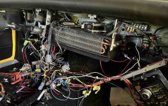
With the engine side of things pretty much done, time to get the dash and wiring sorted out.

Screenshot 2024-08-11 at 8.43.28 PM.jpg

I'm wiring each instrument and switch to its own connector, with a mating one in the car. That way the dash can be removed by easily unplugging all the connectors. Or an individual switch or instrument can be removed.

Getting there.

Rick
 
Last edited:
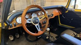
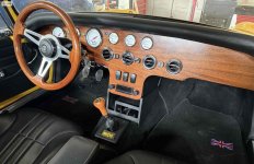
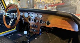
Pretty much done now with the A/C install and the new dash. The details of making the dash are in my other thread: https://www.catmbr.org/cat-forum/threads/making-a-dashboard.8955/

I am really pleased with how this came out. I haven't evacuated and charged the system yet (no sense doing that in the winter), but it does blow a lot of air. The new dash came out great and matches the steering wheel nicely.

Screenshot 2024-12-21 at 7.42.58 PM.jpg

Screenshot 2024-12-21 at 7.43.22 PM.jpg

Still have some tidying up of wires and I want to make something that goes around the lower part of the dash where the radio is. That will hide the wires and allow a clean space below it for some sort of storage bin. I will also add some form of black trim along the bottom of the dash, but don't want it as thick as the stock piece.

So all the mods I set out to do, fuel injection, electric power steering, and A/C are basically complete now. There is a ton of wiring and control boxes behind the dash. Before someone suggests a glove compartment, the new fuse box is behind that area of the dash, so no room.

Rick
 
This thread has morphed into a little more than just adding A/C, but the A/C meant a new dash, and that meant some other related jobs. So the other stuff may be of interest and will answer some questions.

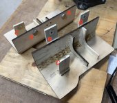
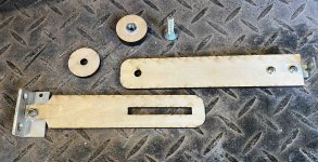
How the centre of the dash is supported. I don't have a picture of it, but just above the radio I epoxied in some threaded inserts to take 1/4" bolts. Then using my laser cutter I made these parts. Yes, could be cut with various other methods, but that is a lot of fun to use; quick, accurate, and easy to cut things like slots. I used it to cut the dash from plywood in several pieces.

Screenshot 2025-01-02 at 5.12.04 PM.jpg

The metal bracket on the lower piece bolts onto the back of the dash right above the radio. The piece above it bolts to a threaded insert near the front of the transmission tunnel. The other hardware connects the 2 pieces and allows adjustment to pull the lower part of the dash back slightly before tightening it. A bit busy, but here it is in place:

Screenshot 2025-01-02 at 5.13.50 PM.jpg

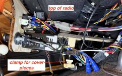
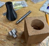
There is an additional block added that will locate and clamp the cover for this area. It has a threaded insert in the bottom of it that the wooden knob/screw threads into. The top of the radio (steel) is pointed out for reference below.

I came up with something I thought would work made from 1/4" plywood to cover the area behind the radio. Without a cover, it looks like this:

Screenshot 2025-01-02 at 5.16.05 PM.jpg

Not nice at all!

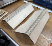
When plywood is cut in a certain way, it can bend. I found files to download these cutting patterns and based the lower dash cover on this principle.

Screenshot 2025-01-02 at 5.16.20 PM.jpg

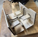
The other side of these pieces look a bit of a complex mess, but here is how it works:

Screenshot 2025-01-02 at 5.16.58 PM.jpg

There are reinforcing pieces to hold the curve. I'm also a fan of using magnets to hold interior pieces in place when you don't want fasteners to show. The magnets 'A' stick to the screwed-in washers 'B' to hold the 2 pieces together. The pieces 'C' with the magnets go over the top of the radio. The magnets adhere to the radio to locate the cover pieces top-to-bottom. This picture shows how they look together:

Screenshot 2025-01-02 at 5.16.38 PM.jpg

The pieces slip in from each side of the lower dash and "magnet" together and to the top of the radio. There is a gap between the 2 pieces that the screw/clamp goes through, into the lower dash support, and clamps the rear of the pieces together and supports them in the up and down direction. Very quick and easy to assemble or remove without any tools.

I had some black headliner material I covered them with. Looks grey in the picture, but it is black:

Screenshot 2025-01-02 at 5.18.53 PM.jpg

The final project (is there ever one?) will be some sort of tray with slide out cup holders to go in front of the shifter and under the radio area. This will be my glove compartment.....should I ever need to store my gloves.

Rick
 
Back
Top