Engine drop plan - and progress

Carbuilder

Gold forum user
Messages
113
I'd check the head thickness to see how far they've been milled. That's the only reason I can think of .80" thick head gaskets....
They were new heads, so don't see a reason for them to be machined. But you did get me thinking...maybe the thick head gasket was to allow for the valve/piston clearance? It does have a fair bit of valve lift (.563" exhaust). But I just removed all the pistons, so don't feel like putting one back in to check the clearance. The cam I have in mind has less lift but I will check the valve/piston clearance when I put it back together. I'm planning on a head gasket about .050 if the new pistons come out of the block the same .010" or so.
 

Austin Healer

Gold forum user
Messages
1,532
.080 ? Lol
Well... .080 is what I meant!! I had to have a copper head gasket made for a Healey at .080, but that was because the previous owner/idiot put the head on the block w/o a gasket and left it that way for several years. The resulting corrosion necessitated a .080 gasket to get the valve geometry back to a point where everything would work.

The only other reason I can think that .080 gaskets would be required is if the block was decked too far and the geometry to fit the intake manifold was impossible. I'd certainly suspect this if the outer part of the crown of the piston was above the deck of the block.

The Aston currently in the shop had the head go soft (electrolytic corrosion)... someone welded it up and warped the snot out of it and ended up taking near 1/8" of an inch of the surface (.125) I advised replacing the head as the valves did interfere with the pistons and there was doubt that the timing chains would properly be tensioned... As a fall back I suggested a solid copper gasket be made at .125"... I was overruled and the client instead de-stroked the engine and bored the liners to give a total displacement of 4.2 litres. It runs, and gave 300HP/300ft. lbs. of torque at 5000 RPM, but... the head is STILL soft and leaks coolant from the top of the head between the plugs. OOPS. it's going to have to come all the way apart and have a new head fitted. Just very happy I had nothing to do with the rebuild.
 
Last edited:

IvaTiger

Gold forum user
Messages
600
Well... .080 is what I meant!! I had to have a copper head gasket made for a Healey at .080, but that was because the previous owner/idiot put the head on the block w/o a gasket and left it that way for several years. The resulting corrosion necessitated a .080 gasket to get the valve geometry back to a point where everything would work.

The only other reason I can think that .080 gaskets would be required is if the block was decked too far and the geometry to fit the intake manifold was impossible. I'd certainly suspect this if the outer part of the crown of the piston was above the deck of the block.

The Aston currently in the shop had the head go soft (electrolytic corrosion)... someone welded it up and warped the snot out of it and ended up taking near 1/8" of an inch of the surface (.125) I advised replacing the head as the valves did interfere with the pistons and there was doubt that the timing chains would properly be tensioned... As a fall back I suggested a solid copper gasket be made at .125"... I was overruled and the client instead de-stroked the engine and bored the liners to give a total displacement of 4.2 litres. It runs, and gave 300HP/300ft. lbs. of torque at 5000 RPM, but... the head is STILL soft and leaks coolant from the top of the head between the plugs. OOPS. it's going to have to come all the way apart and have a new head fitted. Just very happy I had nothing to do with the rebuild.
The electrolytic corrosion was on aluminum heads ? I have never heard of it before on an engine and the tensioning of the timing chain after decking makes sense. Those factors along with others made me go along with my engine being rebuilt be a friend who knows how to do it !
 

Austin Healer

Gold forum user
Messages
1,532
The electrolytic corrosion was on aluminum heads ? I have never heard of it before on an engine and the tensioning of the timing chain after decking makes sense. Those factors along with others made me go along with my engine being rebuilt be a friend who knows how to do it !
yes, probably in the block as well, but not as bad. Astons have alloy heads and blocks with drop in cast iron wet liners for the pistons... use the wrong anti-freeze, or just water and this will happen. I had a Jensen Healey 20 years ago and a Cosworth SCA (Formula Jr. race engine) and they both had the same problem. The new head for the Aston is $15K USD... plus shipping!
 

Carbuilder

Gold forum user
Messages
113
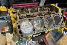
Got the engine all stripped down and ordered new parts. The main and rod bearings are all .010" undersize. I've determined the block was cast 26th August 1987. Not that it matters that specifically, but it is a roller cam 302 block.

I've ordered pistons with 16cc volume, as compared with the 5cc ones in it now. That will bring the compression down from 10.2:1 to 9.7:1. And that's going with a thinner head gasket to give the proper .040-.050 squish; instead of the .070" it has now. Also ordered a Summit intake manifold (equivalent to an Edelbrock Performer). It has a Performer RPM Air Gap now. One reason for the new one is to lower the torque RPM a little, but also the new manifold is about .5" lower. The current air filter has been cut down to prevent the housing from hitting the hood; don't like that at all. Oh, ordered a milder Melling cam too for a smoother idle and lower torque RPM.

Probably going to swap the carb for a fuel injection system. I was thinking of the Sniper 2, but this fairly new company with their Aces Killshot is getting very good reviews. Yes, keeping things stock is not a priority. :)

Rick
 

Carbuilder

Gold forum user
Messages
113
The cam in it is a Trick Flow 51402001. Duration 224 intake, 232 exhaust @ .050", .542/.563 lift, 112 LSA.

I've ordered the Melling SYB-51. Duration 210/211 @.050", .445 lift, 115 LSA.
 

pfreen

Gold forum user
CAT Member
Messages
433
I just installed The Summit 1799 cam. .456 lift and 204 deg duration at .050"
It seems very drivable. My only problem now is an annoying tappet tick. The are all new Summit hydraulic tappets so I need to investigate further.
Unfortunately, with the cast valve covers, I have to lower the engine to get the stupid covers off!
 

0neoffive

Gold forum user
CAT Member
Messages
2,946
I just installed The Summit 1799 cam. .456 lift and 204 deg duration at .050"
It seems very drivable. My only problem now is an annoying tappet tick. The are all new Summit hydraulic tappets so I need to investigate further.
Unfortunately, with the cast valve covers, I have to lower the engine to get the stupid covers off!
Caution about new tappet (lifters). There's plenty of on-line (U tube) comments about them. The manufacturers (?) are missing the fact that there is supposed to be a .002-.003 crown on the bottom (not flat) . A dial indicator run across them at a 90 degree X will reject the flaws and you should send them back. Then there's the cams no longer being "chilled" and requiring a high idle break-in. Collapsing lifters will chew up a fresh cam in no time. The bean counting new engineers need a wake up call.
 

pfreen

Gold forum user
CAT Member
Messages
433
I have read the comments. I thought a Summit cam with Summit lifters would work. We'll see. The tappets are not hammering. They are just noisier than I like.

I broke the cam in carefully so I think it is ok. I'll fix it, but it is a pia.
 

Austin Healer

Gold forum user
Messages
1,532
I have read the comments. I thought a Summit cam with Summit lifters would work. We'll see. The tappets are not hammering. They are just noisier than I like.

I broke the cam in carefully so I think it is ok. I'll fix it, but it is a pia.
There should be zero tappet noise. Are you sure you set them up correctly? With each cylinder at TDC, tighten rocker locknut to zero lash and then tighten 1/2 to one full turn. Interestingly, the Tiger shop manual states two full turns.
 

pfreen

Gold forum user
CAT Member
Messages
433
Yes, They are set correctly. Summit recommends 3/4 turn. All lifter manufacturers have their own setting for lifter preload. My plan is to check to make sure I have the correct pushrods for the cam. If the oem length which I used is correct for the cam, I will readjust and try it.
Then, I will pull the manifold and change the lifters. There is a lot on the web about bad new lifters.
Right now, it is moderate valvetrain noise.
 

Carbuilder

Gold forum user
Messages
113
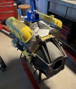
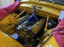
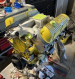
The engine is finally (almost) ready to go back in. It has new pistons, cam, intake, and of course gaskets and seals.

Screenshot 2024-04-17 at 8.21.36 PM.jpg

Due to the height of the polylocks and the roller rockers the engine has a 1/2" aluminum spacers between the heads and the valve covers. So you see 2 gaskets there.

Screenshot 2024-04-17 at 8.20.33 PM.jpg

Screenshot 2024-04-28 at 5.27.25 PM.jpg

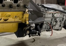
The clutch effort was very high which always bothered me. I think it may be due to this slave cylinder arrangement. It is sort of a reversed system with the cylinder on the front:

Screenshot 2024-04-28 at 5.35.33 PM.jpg

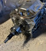
It may be due to the linkage lever arm ratio, but I don't know and can't see how to change it. Also, it comes pretty close to the header on that side. So I've eliminated all of that stuff and am using a hydraulic release bearing:

Screenshot 2024-04-28 at 5.27.45 PM.jpg

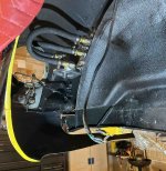
I say the engine is almost ready to go back in, since I need a longer clutch bleed line. There are 2 lines that attach to this bearing; one to the master cylinder, and another that just runs up with a bleeder fitting on it. I need a longer line to make sure I can access the bleed with the engine installed. I"m hoping/thinking this will reduce the clutch effort.

While I've got things apart I changed the remote oil filter mount. That is the only leak the car had. I've run into that before with a remote mount where the leak is where the filter gasket contacts the surface of the mount; no amount of tightening seals it. So I replaced the one I had with a fully machined one from Summit that will hopefully cure the leak.

Screenshot 2024-04-28 at 5.29.08 PM.jpg

I've plumbed the fuel system for the Aces Killshot fuel injection system. Basically had to add a return line to the tank.

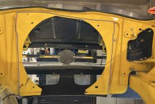
One thing I noticed with the engine and radiator out is how much the radiator is blocked by the surrounding sheet metal. I know it has been trimmed, at least at the bottom. But only the electric fan area has any airflow. I'm thinking of trimming it back to the blue line to open up more airflow area. I'll also block the horn openings.

Screenshot 2024-04-28 at 5.10.58 PM.jpg

I think that is it until the engine goes back in. Since I'm adding A/C and a new dash, it will take a while to figure out where all the dash wires go. Even though I've labelled them, I'm replacing the switches with rocker ones.

Rick
 

0neoffive

Gold forum user
CAT Member
Messages
2,946
Just an airflow suggestion we have learned that really works. Trim back the bottom of the rad support to the width of the existing opening and replace with a 1/2" steel pipe that is flat at both ends for easy welding . The flats need to be on the rear plane of the pipe so the pipe sits forward and not obstruct rad install. Airflow will smoothly go around the pipe and no longer form a forward draft that stalls flow thru the rad bottom. This method also maintains structure.
 

Carbuilder

Gold forum user
Messages
113
Engine back in. Didn't break any time records, but it went well. Took about 1 1/2 hrs. The engine sure has to be in the exact right spot to get the mounts bolted up.

The plan now is to do the minimum electrical and fuel hookups to get it running. Just to run it for less than a minute to make sure it does run. Then finish the install; the other header, the rad and water pump, then run it for longer before putting the front suspension cradle back in.

Screenshot 2024-05-02 at 8.12.47 PM.jpg
 

Carbuilder

Gold forum user
Messages
113
Since I'm swapping from a carburetor to fuel injection, now is the time to do it rather than run it with the carb and then swap. The install involved adding a return line to the tank, installing the high pressure pump, filters, fuel pressure regulator, and the throttle body itself. None of it was too difficult. The only issue is, there are a lot of wires, plus a control box for the fuel injection and another one for the power steering. Lots of stuff to try and hide away.

Screenshot 2024-05-09 at 9.48.38 AM.jpg

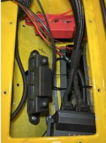
I was thinking of pulling as much as I could into the area between the dash and the firewall, but some of that real estate is used up by the A/C evaporator. Then it occurred to me. When I got the car the heater core was in place but not connected, so I removed it. When installing the A/C I was thinking it is a shame to have that empty pocket of wasted space. Since the evaporator I'm using is heat and A/C I don't need any of the stock heating system. So what a perfect place for all the fuel injection cables:

Screenshot 2024-05-08 at 9.46.33 AM.jpg

To simplify the wiring, I installed 2 heavy duty terminal blocks; 1 for +ve and 1 for ground. I ran a fairly thick wire up from the battery/start connection to the red box and grounded the black one. That way I could connect the +ve and ground leads from the fuel injection, A/C, and the electric power steering unit all in the same place:

Screenshot 2024-06-06 at 8.32.59 PM.jpg

Most of the wiring can now be tucked in. Still some work to do, but it will all fit in. There is the large hole in this compartment leading through the firewall and behind the dash so some of the wires can go into that area.

Screenshot 2024-05-08 at 9.46.21 AM.jpg

With that done, I connected the switches and gauges temporarily to get the engine running.

Screenshot 2024-06-06 at 8.33.41 PM.jpg

I disconnected the coil and cranked the engine until I saw oil pressure. Then connected the coil and cranked it. Got to love fuel injection! Barely a crank and it fired right up and idled. I didn't run it too long since I have no cooling system hooked up.

So now I'm working on swapping the alternator to the other side of the engine to make room for the A/C compressor. Then I'll get the cooling system all put back in and run it for longer to make sure everything is good before putting the front suspension cradle back in. Lots more to do, but looking good.

Rick
 

Carbuilder

Gold forum user
Messages
113
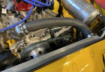
Mounted the cooling fan and the rest of the cooling system. I wanted to run the engine until it warms up to check for leaks or any other issues before putting the suspension cradle back in. The alternator is swapped to the other side in preparation for the A/C compressor to go on the right side.

Screenshot 2024-06-18 at 6.03.06 PM.jpg

I cut the rad opening to better match the size of the rad. Also cut some sheet metal away to mount the fan.

Screenshot 2024-06-21 at 1.04.22 PM.jpg

Screenshot 2024-06-21 at 1.04.42 PM.jpg

The engine ran well. One small coolant leak from where the thermostat housing bolts to the intake manifold. As they say, an easy fix. No oil leaks or any other concerns.....except...

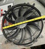
The electric cooling fan blows a lot of air when testing it. But with the rad in front of it (I have a Griffin rad), the flow is cut down to the point that it is hard to tell that air is blowing through the rad. This is what I have now:

Screenshot 2024-06-21 at 1.06.22 PM.jpg

Screenshot 2024-06-21 at 1.06.36 PM.jpg

I'll do some research to see if there is a better one I can get. I do remember the long article on testing all the various cooling mods on a Tiger found that fans with straight blades worked the best. Maybe the curved ones are mainly to quiet it down? Fans on turbofan engines a basically straight, so maybe that says something? Maybe a shroud around the fan would force more air through the rad. I'd like a fan powerful enough to move the car!

Anyways, I can go ahead with things which is good.

Rick

Edit: After looking around a bit, I'm thinking of this fan with a shroud; https://www.summitracing.com/parts/prm-19114
 
Last edited:
Top